|
1.Features:
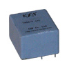
- The primary coil is built-in inside; being able to be directly soldered on
PCB;
- Completely sealed, strong mechanical and environmental endurance, strong dielectric
strength, elegant outline
2.Conditions of usage:
- Circumstance temperature: -55...+85°C;
- Relative humid <90% при 40°C;
- Atmospheric pressure: 860~1060mbar (650~800mmHg approximately);
3.Range of working Frequency: 20Hz~1kHz
4.Insulation Rating: Class F (155°C).
5.Safety features:
- Dielectric resistance: >1000MOm in normal condition;
- Insulation withstand voltages: 6000V 50Hz/1min;
- Fire retardancy: In conformity with UL94-Vo
6.Outline Drawing, Installation Dimention and Coil Diagram
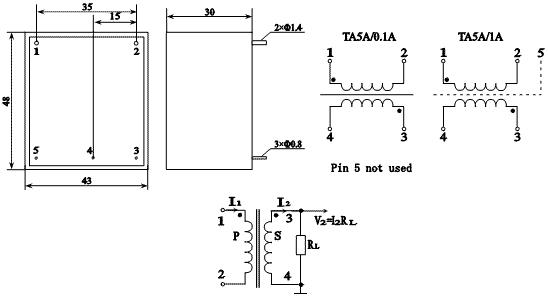
7.Typical Usages and Technical Parameters.
The sampling voltage is obtained directly by using a resistor (as shown in
the right figure).
The parameters are listed in table below.
| Model |
Rated
Input
current |
Rated
Output
current |
Rated
sampling
resistance |
Rated
sampling
voltage |
Phase
Shift |
Non
Linearity |
Linear
Range |
Withstand
Voltage |
| TA5A-0.1A |
5A |
100mA |
30 Om |
3V |
<30` |
<0.5% |
>3 times
of rated
value |
>2kV |
| TA5A-1A |
5A |
1A |
0.3 Om |
0.3V |
Remarks:
a.In practical applications, the sampling resistor should be smaller than or equal
to rated value given in table above in order to improve non-linearity and phase
shift.
b.We can have it customer-made if required current ratio is not listed in the
table above.
8.Attention:
- The primary of the current transformer must be connected in series with the
loop of the measured current. The secondary should operate in a mode of near short
circuit.
- The secondary of the current transformer is not allowed to be open circuit,
Do Not install any fuse.
|